Introduction to DWC HDPE pipes
DWC HDPE pipes – Introduction to modern underground piping solutions begins with understanding their engineering purpose and structural advantages over traditional pipeline materials. Double Wall Corrugated High-Density Polyethylene pipes represent a major progression in civil, mechanical and infrastructure engineering. Although older materials such as concrete, clay, ductile iron and PVC once dominated underground network construction, rising performance expectations and lifecycle cost pressures have driven the transition toward lightweight, flexible and corrosion-resistant systems. Therefore, DWC HDPE pipes have become the preferred choice for telecom ducting, underground cable protection, municipal drainage, highway stormwater management, industrial fluid movement and railway signaling networks.
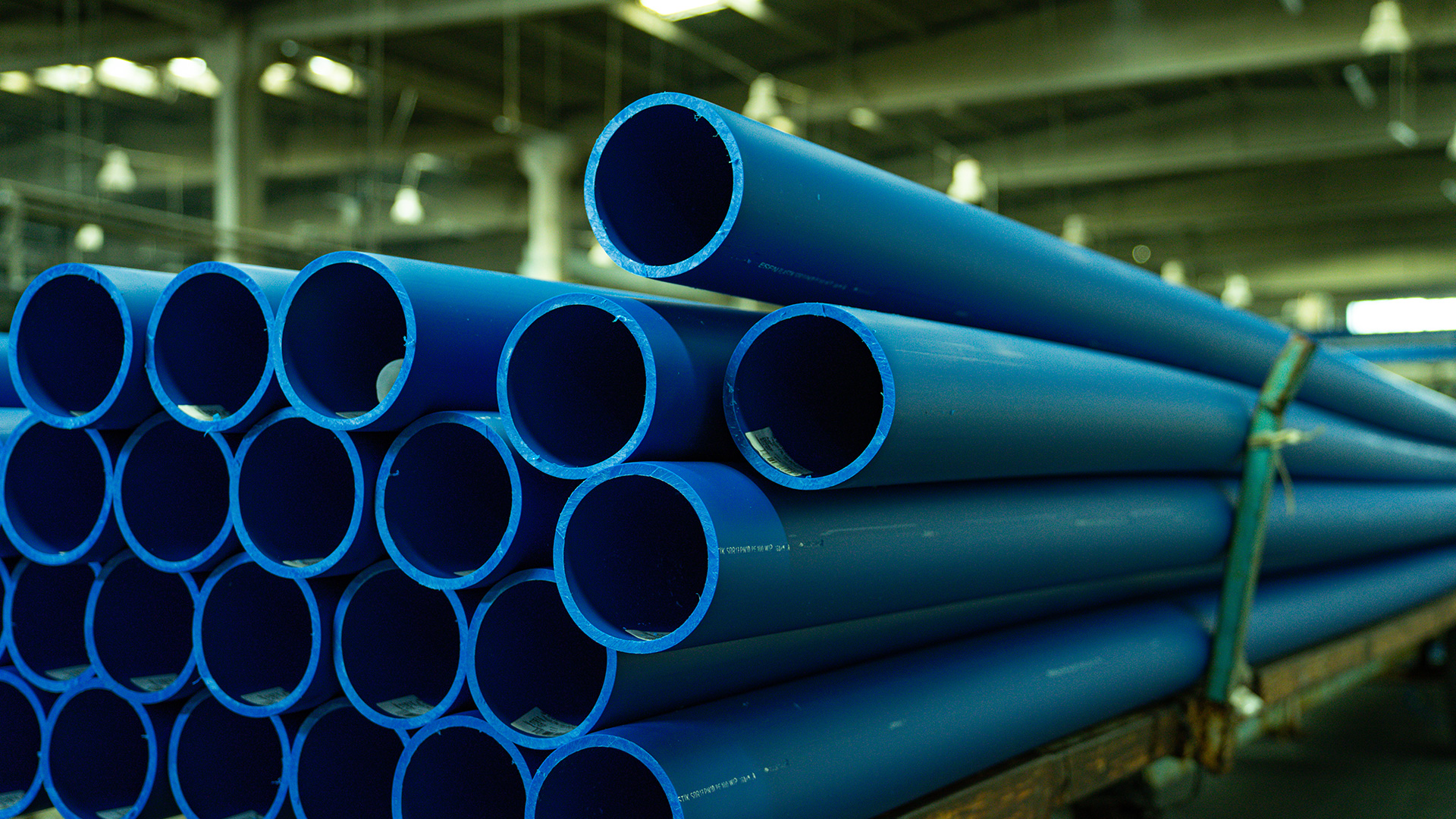
DWC HDPE pipes consist of a dual-layer composite structure. The outer wall is corrugated, delivering exceptional ring stiffness and structural strength under heavy soil cover and dynamic mechanical loads. Meanwhile, the inner wall is smooth, enabling frictionless flow performance and efficient cable pulling. This dual structure allows the pipe to retain geometric stability even during ground movement, vibration and high-transit stress loads. Consequently, projects achieve improved reliability and significantly reduced maintenance cycles throughout operational life.
Because DWC HDPE pipes combine mechanical resilience with ease of installation, they successfully replace heavy rigid pipes across a wide range of infrastructure environments. Additionally, their lightweight nature accelerates trenching operations and reduces equipment dependency, further lowering labor and fuel expenses. Therefore, the combination of strength, flexibility and operational efficiency positions DWC HDPE pipes as a future-proof solution for large-scale infrastructure programs.
Engineering Structure and Material Composition
The structural design of DWC HDPE pipes differentiates them from single-wall alternatives. Although single-layer thermoplastic pipes offer corrosion resistance, they lack the mechanical reinforcement needed for deep burial or road-crossing conditions. As a result, dual-wall construction provides strength without weight penalties.
Outer Corrugated Layer
- Provides high resistance to external compression
- Distributes soil load uniformly
- Minimizes risk of deformation under road or railway vibration
- Enhances stiffness through geometric reinforcement rather than mass
Inner Smooth Layer
- Enables unimpeded flow for stormwater and drainage systems
- Allows high-speed fiber and power-cable installation with minimal friction
- Improves hydraulic performance through reduced drag coefficients
Material Grade
- Produced from Polyethylene PE63, PE80 or PE100 depending on stiffness class
- Includes UV stabilizers and anti-oxidant additives for long-term stability
- Maintains structure between −40°C and +60°C operating temperatures
Because of this engineering composition, DWC HDPE performs consistently in extreme conditions including desert heat, mountain freeze, coastal salinity, chemical treatment and freeze-thaw cycles.
Mechanical Performance Characteristics
Mechanical durability defines infrastructure reliability. Therefore, the performance profile of DWC HDPE pipes plays a crucial role in large public engineering deployments.
Key Performance Attributes
- High Ring Stiffness (SN4, SN6, SN8, SN10 and above)
- Excellent impact and crush resistance
- Superior bending flexibility
- Low surface roughness for uninterrupted flow
- High fatigue resistance under cyclic loading
- Shock absorption under sudden impact
Because the outer corrugation dissipates external forces across multiple ridges, DWC HDPE pipes resist collapse far more effectively than straight-wall alternatives. Additionally, internal smoothness allows predictable flow behavior and reduced pumping losses. Therefore, operational performance remains stable even after decades of service.
Chemical and Environmental Resistance
Chemical resilience is a defining advantage of polyethylene-based structures. Although concrete corrodes in acidic soils and steel oxidizes under moisture or industrial discharge, DWC HDPE pipes remain unaffected by chemical reactions. Consequently, they maintain design capacities without remedial coatings or periodic structural reinforcement.
Resistance Profile
- Acids, alkalis and saline environments
- Industrial and urban wastewater
- Soil bacteria and microbial degradation
- Electrolytic corrosion from underground conductivity
Because environmental damage is eliminated, the lifecycle cost decreases dramatically. Moreover, the absence of internal scaling ensures consistent long-term hydraulic performance. Therefore, industrial effluent and municipal drainage systems prefer DWC HDPE for reliability and safety.

Standards, Testing and Certification
Compliance with global standards ensures predictable product behavior. Therefore, manufacturers and engineers refer to international and national frameworks to define dimensional tolerances and mechanical safety.
Key Specification Standards
- IS 16098 Part 1 & 2 – Structured wall pipes for drainage and cable protection
- IS 4984 / ISO 4427 – Material standards for HDPE resins
- EN 13476-3 – Structured wall piping systems
- BS EN 50086 / IS 14930 – Electrical conduit performance
- AASHTO M 252 / M 294 – Road infrastructure drainage pipes
Because certification guarantees performance reliability, project engineers increasingly include compliance documents in tender qualifications. Additionally, certified systems reduce warranty disputes and inspection delays during commissioning.

Installation Efficiency and Practical Advantages
Efficient installation matters highly to construction projects operating under strict deadlines. Although RCC and metallic pipes demand cranes and high labor effort, DWC HDPE pipes reduce installation complexity significantly. As a result, project execution speeds increase.
Installation Benefits
- Lightweight structure simplifies handling and transport
- Rapid trench placement without heavy machinery
- Fewer joints needed due to long lengths
- Flexibility supports curved routing without elbows
- Compatible with trenchless drilling and micro-tunneling
- Lower breakage risk during backfilling
- Minimal surface disruption in urban zones
Because installation becomes simpler and faster, total project expenditure drops. Furthermore, reduced surface impact is essential for metro rail corridors, IT parks, smart-city duct routing and airport redevelopment where access windows are restricted.
Major Application Areas of DWC HDPE Pipes
DWC HDPE is deployed across multiple engineering sectors. Although originally introduced for cable protection, adoption has expanded dramatically due to structural versatility.
Telecom and Fiber Optic Networks
5G and high-speed broadband expansion demand reliable underground ducting. The smooth inner bore decreases pulling tensions and eliminates sheath damage, therefore increasing cable lifespan.
Railway and Metro Signaling Networks
High ring stiffness ensures structural stability under ballast impact and vibration. Therefore, signaling circuits remain protected for decades even beneath passenger and high-speed freight trains.
National Highways and Road Drainage
Stormwater management beneath highways requires pipes capable of handling repeated heavy-axle loads. DWC HDPE absorbs external pressure without cracking, therefore reducing flooding risk.
Municipal Sewer Systems and Urban Drainage
Hydraulic efficiency improves flow and prevents sediment buildup. Because corrosion is eliminated, replacement frequency declines sharply.
Industrial Effluent Networks
Chemical processing units discharge fluids aggressive to concrete. DWC HDPE prevents leakage and structural decay.
Smart City Utility Corridors
Multiple service conduits routed together benefit from flexible alignment and lightweight installation.
Power Cable Protection
DWC HDPE protects HT / LT underground circuits from soil stress and environmental deterioration.
Because performance covers diverse sectors, adoption rates rise steadily across infrastructure portfolios.
Jointing Systems and Compatibility
Jointing flexibility allows DWC HDPE pipes to integrate into both pressurized and non-pressurized systems.
Supported Jointing Types
- Push-fit couplers
- Rubber ring sealing joints
- Heat shrink sleeve sealing
- Electrofusion systems for high integrity
Because joint selection adapts to environmental constraints, engineering control improves significantly. Therefore, leakage and infiltration risks reduce substantially.
Ring Stiffness Engineering
Ring stiffness defines the pipe’s capability to resist radial collapse under pressure loads. Therefore, stiffness selection must consider soil type, cover depth and surface traffic.
| Stiffness Class | Recommended Usage Environment |
|---|---|
| SN4 | Light traffic, landscaping and pathways |
| SN6 | Medium load utility corridors |
| SN8 | High-traffic commercial roadways |
| SN10+ | Rail, airport and deep burial conditions |
Because of grade flexibility, DWC HDPE suits both civilian and heavy-duty industrial infrastructures.
Environmental Sustainability and Lifecycle Value
Sustainable infrastructure requires materials that minimize carbon footprint and support circular economy policies. HDPE resin manufacturing consumes less energy compared to metal or cement-based pipelines. Moreover, pipes remain recyclable.
Sustainability Benefits
- Lower transportation emissions due to lightweight profile
- Reduced energy usage during production
- Fully recyclable polymer structure
- Lower maintenance waste generation over 50+ year lifespan
Therefore, DWC HDPE pipes align with sustainability certifications and ESG targets.
Engineering Challenges and Precautions
Although these pipes provide superior performance, improper installation may reduce efficiency. Therefore, engineering best practices require adherence.
Key Risk Points
- Bedding preparation failures
- Incorrect backfill compaction
- Poorly aligned joints
- Sharp rock contact damaging corrugation
- Ignoring minimum bending radius guidelines
Because most failures arise from installation errors rather than product weakness, trained crews and engineering oversight remain essential.
Summary
DWC HDPE Pipes – Introduction demonstrates the performance evolution of underground pipeline technology. As infrastructure complexity increases, lightweight flexible materials capable of high mechanical resistance gain priority over traditional rigid systems. Because dual-wall corrugated construction combines compression strength with hydraulic efficiency, DWC HDPE ensures reliable performance across telecom networks, metro and railway signaling corridors, highway drainage systems, utility tunnels and industrial effluent environments. Therefore, its adoption continues growing rapidly as lifecycle economics and installation speed become crucial determinants of project feasibility.
Installation Engineering and Structural Design Parameters
Although material strength defines baseline durability, installation engineering determines actual operational longevity of underground systems. Therefore, correct trench design, bedding preparation and load distribution planning remain essential when working with DWC HDPE pipes. Because installation methods influence deformation behavior under external pressure, engineers must adapt trench profiles to soil type, traffic category and target stiffness class.
Trenches must provide uniform bedding support. Dry sand or granular soil with controlled compaction offers optimal cushioning for corrugated profiles. Additionally, trench walls require stability to prevent sidewall pressure points that could distort pipe geometry. Therefore, the foundation must remain free from sharp aggregates, construction debris and oversized stones. When soil conditions remain unstable due to high moisture or clay density, geotextile reinforcement may be installed beneath the bedding layer to distribute loads evenly.
Backfill material placement requires structured compaction. Engineers typically compact in layers of 150–300 mm depending on trench depth and surface load expectations. Meanwhile, controlled moisture content ensures uniform consolidation. Because uneven compaction causes point load failure, backfilling cannot be rushed. Furthermore, mechanical compactors must not touch the pipe surface. Instead, hand tampers or small plate compactors support compaction adjacent to the pipe until 300 mm cover is achieved.
Minimum bending radius recommendations are critical during route alignment. DWC HDPE pipes allow curvature adjustment without elbows, although bending beyond tolerance risks structural deformation. Therefore, routing plans incorporate smooth curves rather than angular offsets. Additionally, trenchless methods such as horizontal directional drilling (HDD) or micro-tunneling demand calibrated pulling pressures and lubrication planning to prevent internal deformation.
Load Simulation and Stress Analysis
Structural performance verification relies on load simulation models including finite element analysis (FEA). Because DWC HDPE pipes must withstand static and dynamic loads, engineers simulate soil pressure, wheel impact cycles, vibrational forces, buoyancy effects in saturated soils and differential settlement. Moreover, stress models help determine appropriate ring stiffness class selection and acceptable burial depth.
Vertical loads originate from the weight of soil layers and traffic movement. Meanwhile, lateral loads arise from trench wall friction and soil displacement. Because dynamic loads transfer differently through corrugations compared to solid pipes, ridge spacing and corrugation height directly influence deformation characteristics. Therefore, selecting SN4, SN6, SN8 or SN10 stiffness classes requires analytical accuracy rather than assumption based planning.
Railway or highway installations demand higher stiffness grades. The cyclic stress generated by axle movement can induce fatigue failure in rigid pipes. However, DWC HDPE flexes elastically and absorbs cyclic energy, therefore extending the fatigue life significantly. Airports require SN10 or higher due to concentrated wheel loads exceeding standard commercial vehicle ratings. Additionally, engineers evaluate impact loads caused by construction machinery operating above trench paths. Consequently, safety margins account for both operational and installation-stage loading.
Buoyancy risk must be evaluated when pipes are installed in high ground water environments. Lightweight materials may float if backfill compaction is inadequate or if trench flooding occurs before stabilization. Therefore, anchoring systems or increased cover depth eliminate uplift hazards. Furthermore, trench drainage channels divert water to prevent hydraulic uplift during extreme weather.
Application-Specific Engineering Requirements
Although core design principles remain consistent, application environments dictate unique configuration parameters. Therefore, engineers modify installation architecture based on performance expectations.
Telecom and Fiber Optic Cable Routing
Telecommunication projects prioritize smooth internal surfaces to minimize friction and avoid microfiber strain. Although pulling forces depend on distance and cable type, lubricated internal surfaces reduce mechanical stress significantly. Therefore, long-span installations frequently use continuous reel lengths to minimize joint count. Additionally, access pits and cable chambers integrate with duct banks for distribution planning.
Municipal Sewer and Drainage Lines
Gravity-based flow networks require consistent gradients. Because flow efficiency depends on smooth bore characteristics, HDPE provides predictable hydraulic performance. Furthermore, wastewater systems need leak-proof joints and corrosion immunity. Therefore, rubber ring-sealed connections deliver reliable leak resistance. In industrial effluent projects, engineers integrate high chemical compatibility and airtight sealing to prevent contamination.
Highway Stormwater Management
Stormwater design requires fast hydraulic discharge under fluctuating flow rates. Because DWC HDPE has low Manning’s roughness values, flow velocity remains high even when pipes operate partially filled. Additionally, corrugated structure absorbs external compression from highway load cycles and soil settlement. Therefore, surface flooding risks and road base erosion reduce substantially.
Railway Signalling and Electromagnetic Shielding
Cabling ducts experience vibration from high-speed train movement and ballast particle shifts. Because rigid pipes crack under vibration, flexible HDPE preserves integrity. Additionally, electromagnetic shielding requires protective spacing between circuits. Therefore, engineers design duct banks with isolated chambers, minimizing interference risk.
Comparing DWC HDPE to RCC, PVC, GI and Concrete Pipes
Material replacement trends rely heavily on performance and lifecycle value. Although RCC and GI pipes once dominated underground networks, practical limitations accelerate their phase-out.
| Criterion | DWC HDPE Advantage | Traditional Pipe Limitation |
|---|---|---|
| Weight | Extremely lightweight; easy to handle without cranes | Heavy; requires lifting equipment |
| Flexibility | High bending capability; adapts to terrain | Rigid; cracks under settlement |
| Corrosion | Immune to chemical attack | Severe corrosion in saline or polluted soil |
| Installation speed | Fast trench placement | Slow, labor-intensive |
| Jointing | Push-fit or sealing rings; low leak risk | Joint cracking and infiltration |
| Hydraulic efficiency | Smooth bore; lower friction | Internal roughness increases flow resistance |
| Maintenance | Minimal; 50+ year lifespan | High repair cycles and leakage |
HDPE Comparison With other Pipes
RCC Pipes
| Parameter | HDPE (DWC / Solid Wall) | RCC (Reinforced Concrete Cement) |
|---|---|---|
| Material structure | High-density polyethylene, flexible dual/solid wall | Concrete with embedded steel reinforcement |
| Weight | Very light (8–12 kg/m) | Very heavy (180–550 kg/m) |
| Installation speed | Fast, low machinery requirement | Slow, requires cranes & large crew |
| Joint type | Push-fit / welded / gasket sealed | Bell & spigot with rubber rings / cement |
| Leakage risk | Very low due to flexible joints | High due to rigid joints and cracking |
| Chemical resistance | Excellent | Very poor under industrial and acidic exposure |
| Corrosion resistance | Full resistance | Prone to corrosion and internal scaling |
| Earth movement response | Absorbs ground movement | Cracks under structural movement |
| Soil load bearing | Engineered through flexibility | Rigid load bearing |
| Maintenance | Minimal | Frequent and expensive |
| Life expectancy | 75–100 years | 25–40 years |
| Cost installation | Low | High (machinery & labour intensive) |
| Best use cases | Drainage, sewage, underground ducting, telecom | Non-pressure storm drains, culverts |
PVC Pipes
| Parameter | HDPE | PVC (Polyvinyl Chloride) |
|---|---|---|
| Flexibility | High, bend radius up to 20–30x OD | Rigid, breaks under bending |
| Pressure shock resistance | Excellent | Weak under surge / water hammer |
| Joint sealing | Welded or push-fit | Solvent / gasket / mechanical |
| UV resistance | High with carbon-black | Moderate, requires coating |
| Temperature range | -40°C to +60°C | 0°C to +45°C |
| Chemical resistance | Very high | Good but deteriorates with solvents |
| Impact resistance | Very high | Low at low temperatures |
| Installation | Trenchless compatible | Limited flexibility |
| Durability in buried networks | Excellent | Average |
| Recyclability | High | Low (additives contamination) |
| Best use | Sewer, telecom ducts, water supply | Light irrigation, internal plumbing |
GI Pipes
| Parameter | HDPE | GI (Galvanized Iron) |
|---|---|---|
| Corrosion | Zero corrosion | Severe corrosion in soil and water |
| Surface roughness | Smooth wall – high hydraulic efficiency | Decreases over time due to scaling |
| Internal friction loss | Low | High |
| Joint method | Heat fusion / mechanical | Threaded / flanged |
| Leakage rate | Very low | High due to joint deterioration |
| Weight | Light | Very heavy |
| Installation | Quick | Very slow |
| Life expectancy | 75–100 years | 15–25 years depending on water quality |
| Chemical resistance | High | Very low |
| Pressure handling | Good | Good initially but degrades fast |
| Maintenance | Minimal | High recurring replacement cost |
| Cost | Lower total lifecycle cost | Highest long-term cost |
| Best application | Water supply, sewer, effluent lines | Fire lines, temporary water connections |
Summary Table – Overall Comparative Insight
| System Type | Durability | Flexibility | Installation Cost | Maintenance | Ideal Applications |
|---|---|---|---|---|---|
| HDPE (DWC / PE100) | ⭐⭐⭐⭐⭐ | ⭐⭐⭐⭐⭐ | Low | Very Low | Sewer, stormwater, telecom, culverts, industrial discharge |
| RCC | ⭐⭐⭐ | ⭐ | Very High | High | Culverts, gravity drains requiring rigid form |
| PVC | ⭐⭐ | ⭐⭐ | Medium | Medium | Internal plumbing, low-pressure piping |
| GI | ⭐⭐ | ⭐ | High | Very High | Temporary water lines, fire hydrants |
Because infrastructure budgets now prioritize lifecycle advantage, replacement frequency strongly benefits HDPE systems.
Applications, Standards, Testing & Installation Engineering
Applications of DWC HDPE Pipes Across Sectors
DWC HDPE Pipes function as structural conduits engineered for subsurface and surface utility integration. They support gravity flow systems and protect critical infrastructure assets. Their dual-layer architecture delivers strength while maintaining lightweight flexibility. Therefore, they dominate sectors requiring performance under dynamic environmental stress.
Sewer & Stormwater Drainage
Municipal drainage networks prefer DWC HDPE due to corrosion resistance and shock absorption capacity. Sewer lines depend on uninterrupted flow. Consequently, smooth bore interiors minimize friction losses and prevent sedimentation. Adequate slope engineering allows high discharge velocity without material degradation.
Underground Electrical & Telecom Ducting
Fiber backbone networks and power utilities adopt DWC HDPE conduits for cable protection. Additionally, trenchless horizontal directional drilling (HDD) supports long-distance underground routing without road excavation. Therefore, telecom expansion accelerates and restoration delays diminish.
| Parameter | Telecom Expectations | DWC HDPE Advantage |
|---|---|---|
| Flexural radius | Low bend radius tolerance | Maintains curvature without fracture |
| Pulling force | High stress during cable pulling | Absorbs tensile load |
| Water ingress | Forbidden | Leak-proof push-fit joints |
Railway & Highway Crossings
Road and rail corridors require heavy-load stability. Distributed stress resistance makes DWC HDPE ideal beneath pavements. Additionally, its ribbed exterior enables soil-pipe interaction that absorbs shock from moving loads.
Culverts & Irrigation Networks
DWC pipes replace RCC in irrigation, culverts and flood channels due to rapid installation and chemical resistance. Therefore, lining failures reduce sharply.
Industrial Effluent & Chemical Slurry
Industrial waste lines demand anti-corrosive capability. Acidic and alkaline fluid resistance of HDPE eliminates scaling, rusting and brittle fractures. Consequently, effluent plants achieve lower downtime.
Airport & Port Infrastructure
Runway crossings and port stormwater systems depend on high-strength conduits. Although extreme weight loads apply, DWC HDPE performs under static and live load pressures.
Standards & Classifications of DWC HDPE Pipes
Manufacturing compliance aligns with performance reliability. Standards define mechanical tolerance, ring stiffness class, melt flow index and density. Therefore, certified products ensure fail-safe installation.
Key Indian & International Standards
| Standard | Description |
|---|---|
| IS 16098 Part 1 & 2 | Governs DWC pipes for drainage and sewer |
| IS 4984 / IS 14333 | Pressure HDPE pipes for water & effluent |
| DIN 16961 | Structural design & ring stiffness classification |
| ISO 4427 / 4437 | Water & gas HDPE performance compliance |
| EN 13476 | Structured wall thermoplastic pipes testing |
Ring Stiffness (SN Rating)
| SN Class | Application Area | Primary Benefit |
|---|---|---|
| SN2 | Low-depth residential corridors | Lightweight, low-burial cost |
| SN4 | Urban roads & pedestrian zones | Moderate traffic resistance |
| SN8 | Highways, industrial zones | Heavy vehicle load support |
| SN12 / SN16 | Airports, ports, railway corridors | Maximum ground load capacity |
Engineering Considerations for Safe Installation
Correct installation preserves structural performance. Therefore, trench profile, bedding preparation and joint sealing must follow engineering controls.
Trenching & Bedding
A stable trench supports pipe wall geometry. Bedding prevents point loads from angular stones or debris.
Trench Design Parameters
| Component | Requirement |
|---|---|
| Bed layer | 100–150 mm sand or fine soil |
| Side packing | Compacted soil around ribs |
| Cover depth | ≥ 600 mm for light loads |
| Highway depth | ≥ 900 mm for heavy loads |
| Max trench width | Pipe OD + 300 mm |
Slope & Flow Velocity
Sewer flow efficiency depends on gradient control. Therefore, slopes vary based on pipe diameter.
| Diameter | Minimum Slope |
|---|---|
| 160–250 mm | 0.5 – 1.0% |
| 300–400 mm | 0.3 – 0.5% |
| 500–800 mm | 0.2 – 0.3% |
Jointing Techniques
| Method | Usage | Note |
|---|---|---|
| Coupler / Push-fit | Stormwater, telecom | Quick installation |
| Electrofusion / Butt Fusion | Industrial fluids | Pressure sealing |
| Rubber Sealing Ring | Sewer gravity lines | Prevents inflow/outflow |
Compaction
Layer-by-layer compaction avoids pipe floating and deformation. Additionally, correct compaction maintains ring stiffness performance.
Testing & Quality Assurance
Field tests verify structural endurance and leak resistance. Therefore, pipelines must undergo validation before commissioning.
| Test | Purpose | Frequency |
|---|---|---|
| Hydrostatic Test | Leak integrity | Every section |
| Air Pressure Test | Joint sealing check | Manhole-to-manhole |
| Mandrel Test | Deflection control | 30-day evaluation |
| CCTV Inspection | Flow alignment | Post-backfill |
Deflection < 5% of internal diameter ensures structural stability.
Failure Modes & Prevention Strategies
| Cause | Effect | Prevention |
|---|---|---|
| Poor bedding | Cracking | Sand cushioning |
| Low compaction | Ovality | Tiered compaction |
| Misalignment | Joint leakage | Laser alignment tools |
| Rapid backfill | Pipe distortion | Controlled layering |
Consequently, engineering discipline ensures pipeline lifespan exceeding 100 years.
Lifecycle Cost & Economic Advantage
Total Cost of Ownership (TCO) favors DWC HDPE through reduced installation cost, minimal repair and longer service life. Although initial pipe unit pricing may exceed RCC or PVC, lifecycle savings exceed 35–60%.
| Expense Category | HDPE Cost Outcome |
|---|---|
| Machinery | Minimal |
| Labor | Reduced crew requirement |
| Transport | Lightweight & compact shipping |
| Repairs | Very rare |
| Replacement cycle | Longest |
Future Trends & Material Innovations
Next-Generation DWC Pipe Technologies
- Nano-stabilized HDPE resin
- Graphene-reinforced polyethylene
- Smart sensor-embedded monitoring
- AI-optimized trench models
- Solar trenchless installation supports
- Microwave-based pipe welding
Urban infrastructure modernization demands durability with minimal environmental burden. Therefore, HDPE adoption increases globally.
Sustainability
Recyclability makes HDPE a circular-economy material. Consequently, carbon footprint reduces versus cement-intensive RCC.
Conclusion
DWC HDPE Pipes redefine underground utility engineering. They combine structural performance, corrosion resistance, installation efficiency and lifecycle economy. Their reliability under dynamic loads and diverse environmental conditions positions them as the preferred alternative to RCC, PVC and GI pipelines. Therefore, government utilities, industrial zones, highways, irrigation departments, telecom operators and smart-city infrastructure prefer DWC HDPE systems for long-term resilience and cost-controlled deployment.
DWC HDPE pipelines enable future-proof infrastructure. Their engineering superiority becomes evident wherever reliability, speed and durability determine project feasibility.
Cost Efficiency and Economic Modeling
Cost evaluations extend beyond material prices. Although the initial cost per meter may appear higher compared to concrete or clay, lifecycle expenditure analysis demonstrates total savings across deployment and maintenance phases. Therefore, infrastructure planners favor DWC HDPE when evaluating long-term feasibility.
Cost Optimization Drivers
- Lower transportation and handling expenses
- Faster installation reducing labor hour accumulation
- Minimal equipment rental such as cranes and loaders
- Reduced downtime and operational disruptions
- Lower repair and replacement frequencies
Additionally, trench width may narrow significantly due to lighter pipe handling requirements. Consequently, excavation costs reduce. Because urban trenching often drives major financial overhead, narrowing trench width produces measurable savings.
Furthermore, trenchless installation eliminates surface rehabilitation expenses. HDD reduces road-break costs, enabling uninterrupted traffic and lower municipal penalty exposure. Therefore, infrastructure programs in dense metropolitan areas increasingly specify DWC HDPE for duct routing beneath intersections, railway stations and airport zones.
Future Material Science and Manufacturing Innovations
Material innovation continues to strengthen performance capabilities. Advances in polymer formulation, corrugation geometry optimization and extrusion processing improve consistency and structural behavior.
Development Trends
- Higher molecular weight polyethylene grades for increased stress crack resistance
- Smart pipe variants with embedded sensor channels for remote monitoring
- Foam core lightweight structures improving insulation and rigidity balance
- Bi-modal resin technology enhancing flexibility without strength loss
- Manufacturing automation improving accuracy and dimensional tolerance
Additionally, integrated RFID traceability supports asset management in utility corridors. Therefore, maintenance teams track underground infrastructure digitally, reducing detection time.
Environmental Sustainability and Carbon Impact
Global construction policy demands sustainable materials. Because DWC HDPE provides full recyclability and low carbon production values, sustainability compliance improves dramatically.
Lifecycle Indicators
- Reduced CO₂ emissions from manufacturing and transport
- Decreased landfill waste due to long service life
- Recycling loops for end-of-life materials
- Reduced water contamination risk due to corrosion resistance
Therefore, green building certification systems including IGBC and LEED increasingly specify HDPE-based infrastructure as preferred pipe material for smart cities and sustainable public engineering.
Case-Based Engineering Validation
Multiple national and international infrastructure projects validate performance through real-world conditions.
Example Environments
- Metro rail ducting corridors under vibration load
- Airport drainage beneath extreme wheel load pressures
- Offshore coastal chemical exposure regions
- Desert terrain with extreme temperature cycling
- Heavy monsoon stormwater discharge
Because performance remains consistent across diverse landscapes, engineers deploy DWC HDPE as a universal solution rather than project-specific material.
Understanding of DWC HDPE Pipes
This section expands the understanding of DWC HDPE Pipes – Introduction by outlining engineering installation methods, stress models, material selection strategies and application-driven performance considerations. Because infrastructure scale and operational demands continue intensifying, the advantages of lightweight, flexible, corrosion-resistant and long-life pipelines dominate procurement logic. Therefore, combined lifecycle, cost modeling and engineering predictability accelerate global adoption across telecom, drainage, highways, rail transit, industrial effluent and smart city utilities.
Failure Modes, Quality Assurance and Risk Mitigation
Although DWC HDPE pipes demonstrate exceptional performance across utility infrastructure, engineering reliability depends on understanding failure triggers. Consequently, predictive maintenance strategies and quality-controlled processes minimize risk. Additionally, failure analysis helps determine tolerance limits under extreme conditions.
The most common failure categories include installation-induced deformation, joint leakage due to misalignment, external impact distortion from inadequate bedding, UV degradation during prolonged storage and over-stress conditions arising from excessive burial depth. Because most failures originate from procedural deviations rather than material weakness, adherence to installation standards remains essential.
Manufacturing defects represent another risk cluster. Therefore, dimensional inspection, ring stiffness testing and impact resistance validation occur before dispatch. ISO standards enforce controlled extrusion temperature, uniform wall thickness and corrugation symmetry. Additionally, sampling-based tensile strength tests ensure material integrity complies with specified grade levels. Meanwhile, surface continuity inspection eliminates micro-cracking risks that could expand under load stress.
Furthermore, engineers verify jointing reliability through negative pressure and hydrostatic pressure testing. Vacuum tests simulate backflow conditions routinely experienced within municipal drainage and sewer networks. Therefore, joint design precision directly influences long-term leak resistance. Although push-fit joints prove sufficient for standard interfaces, high-pressure waste networks may require electrofusion or butt fusion welding to increase seal strength. Consequently, joint selection must align with network pressure profiles rather than universal assumptions.
Project Deployment Workflow
Large-scale utility projects demand structured deployment frameworks with integrated resource planning. Therefore, phased execution improves predictability and safeguards installation quality.
Phase 1 – Route Survey and Utility Mapping
Engineers begin with digital topography mapping, geotechnical analysis and subsurface utility detection. Because underground conflict risk remains high in urban corridors, ground-penetrating radar (GPR) and electromagnetic locators generate conflict matrices. Meanwhile, municipal authorities provide existing drawing archives. Additionally, terrain variation analysis identifies slope correction requirements for gravity systems. Consequently, early detection eliminates redesign delays.
Phase 2 – Material Specification and Quantity Planning
Procurement teams finalize pipe diameter, ring stiffness grade, jointing type and structural reinforcement requirements. Although diameter selection depends on flow calculations based on peak discharge models, future scalability must also be considered. Therefore, infrastructure design rarely selects minimum viable diameter. Additionally, project scheduling synchronizes material delivery to prevent onsite storage stress and UV exposure.
Phase 3 – Trench Engineering and Installation Execution
After excavation, foundation bedding stabilizes load distribution. Because installation depends heavily on compaction uniformity, quality inspectors evaluate layer density using field compaction tests. Meanwhile, trench geometry follows gradient control lines established with optical or laser leveling systems. Consequently, hydraulic consistency improves significantly.
Phase 4 – Jointing and Alignment Precision
Alignment lasers maintain internal straightness across long spans. Additionally, lubrication assists gasket seating without torsion. Because joint stress amplification occurs with angular misalignment, straight alignment checks verify acceptable tolerance levels. Furthermore, anchor blocks prevent longitudinal pipe movement during pressure cycles.
Phase 5 – Testing and Validation
Hydrostatic pressure tests, low-pressure air tests and mandrel tests validate structural performance. Because mandrel test failure exposes deformation hotspots caused by compaction issues, corrective backfilling resolves stress concentration points. Additionally, CCTV inspection evaluates internal smoothness and joint uniformity. Therefore, validation confirms service readiness before road reinstatement and surface stabilization.
Phase 6 – Documentation and Handover
Digital GIS mapping records pipe location, depth profile, joint positions and access chamber coordinates. Because modernization demands asset visibility, digital documentation becomes as critical as physical installation.
Design Calculations and Hydraulic Modelling
Hydraulic efficiency determines pipeline sizing. Although Manning’s equation remains standard for open channel flow modeling, HDPE’s low roughness coefficient enhances discharge capability.
Key Calculation Considerations
- Peak flow rate and storm return interval
- Slope gradient and hydraulic head loss
- Flow velocity thresholds to prevent deposition
- Diameter selection for future network expansion
- Air entrainment behavior in partial flow conditions
Although rigid pipes require higher diameters to compensate for surface resistance, HDPE maintains consistent hydraulic behavior even at smaller diameters. Therefore, capacity management improves.
Finite element flow simulations evaluate turbulence zones, surcharge conditions and transient pressure spikes. Because transient effects generate pipeline vibration and joint pressure amplification, surge control strategies integrate relief valves and dissipation chambers. Therefore, protective engineering eliminates water hammer risks.
Performance Validation Under Extreme Environments
Although standard urban networks represent controlled conditions, DWC HDPE pipes have demonstrated exceptional resilience in harsh and unpredictable environments. Therefore, they remain preferred material for locations demanding extreme reliability.
High Salinity Coastal Regions
Corrosion remains the dominant failure driver in coastal installations. Because HDPE displays full resistance to chloride and sulfate, structural life remains stable. Meanwhile, concrete and metal degrade rapidly due to ionic corrosion. Therefore, long-term maintenance costs reduce significantly.
Desert Climates with Temperature Swings
Temperature cycles between 4°C nights and 48°C days create expansion stresses. Although rigid materials fracture under thermal delta, DWC HDPE flexes without damage. Therefore, continuous service becomes achievable under desert expansion dynamics.
Flood and Waterlogging Zones
Floating risks affect lightweight materials. However, increased cover depth and structured backfill effectively eliminate uplift forces. Additionally, buoyancy modeling protects pipeline stability.
Seismic Zones
Earthquake-prone regions require flexible ducting capable of absorbing ground shifts. Because DWC HDPE demonstrates high strain tolerance, breakage incidents drop substantially.
Lifecycle Maintenance and Monitoring
Although DWC HDPE pipelines demand minimal maintenance, preventive procedures improve operational reliability. Therefore, maintenance schedules include CCTV inspections, manhole access cleaning, hydraulic flushing and joint seal verification.
Additionally, emerging smart pipe architectures integrate sensors to track vibration, pressure shifts and groundwater interaction. Therefore, real-time monitoring enables predictive maintenance.
Maintenance intervals depend on application type. While cable duct networks may require minimal intervention, stormwater channels collect sediment. Therefore, flushing operations maintain discharge efficiency.
Future Outlook of Structured Wall Polymer Piping Systems
Infrastructure evolution depends increasingly on lightweight, durable and recyclable materials. Therefore, structured wall polymer systems will dominate next-generation public and industrial utilities. Additionally, research directions focus on material optimization, smart sensing integration and automation-driven manufacturing.
Key Growth Catalysts
- Smart city network expansion across global markets
- Telecom fiber acceleration due to 5G and data center scaling
- Climate resilience infrastructure investments
- High-efficiency drainage planning for rapid urbanization
- Sustainable materials replacing concrete and metal
Additionally, international standard harmonization strengthens global adoption. Because performance requirements remain consistent across climate variations, cross-border project deployments accelerate significantly.
Comprehensive Advantages Summary
Although cost often drives material selection, engineering reliability and lifecycle performance define long-term feasibility. Therefore, DWC HDPE remains superior across mechanical, hydraulic and environmental dimensions.
Primary technical advantages
- Lightweight handling and fast installation
- High flexibility and vibration tolerance
- Superior corrosion and chemical resistance
- Smooth internal surface increasing hydraulic flow
- Long service life with minimal maintenance
- Recyclable and environmentally positive
- Reliable joint integrity with low leakage risk
Conclusion
The global engineering transition toward sustainable, high-performance underground utility materials places structured wall polymer systems at the core of modern infrastructure. Therefore, DWC HDPE Pipes – Introduction reflects a new construction paradigm where strength, flexibility and durability coexist without compromise. Because complex urban networks require adaptable, resilient and cost-efficient solutions, DWC HDPE pipelines deliver measurable advantages across telecom, drainage, industrial effluent, smart cities, highways and rail transit infrastructure.
Ultimately, strategic deployment and controlled installation transform DWC HDPE into a long-life asset capable of supporting decades of high load service. Therefore, procurement strategies worldwide continue shifting, replacing legacy rigid piping systems with advanced dual-layer polymer architecture to meet future performance expectations.
